Code for section 1Controls
Mechanical Design
Software/Electronics
Controls
Full code on my Github: https://github.com/VimalVasu/2DBallBalancer/tree/main
Goal for ball balancer robot:
(Work in progress)
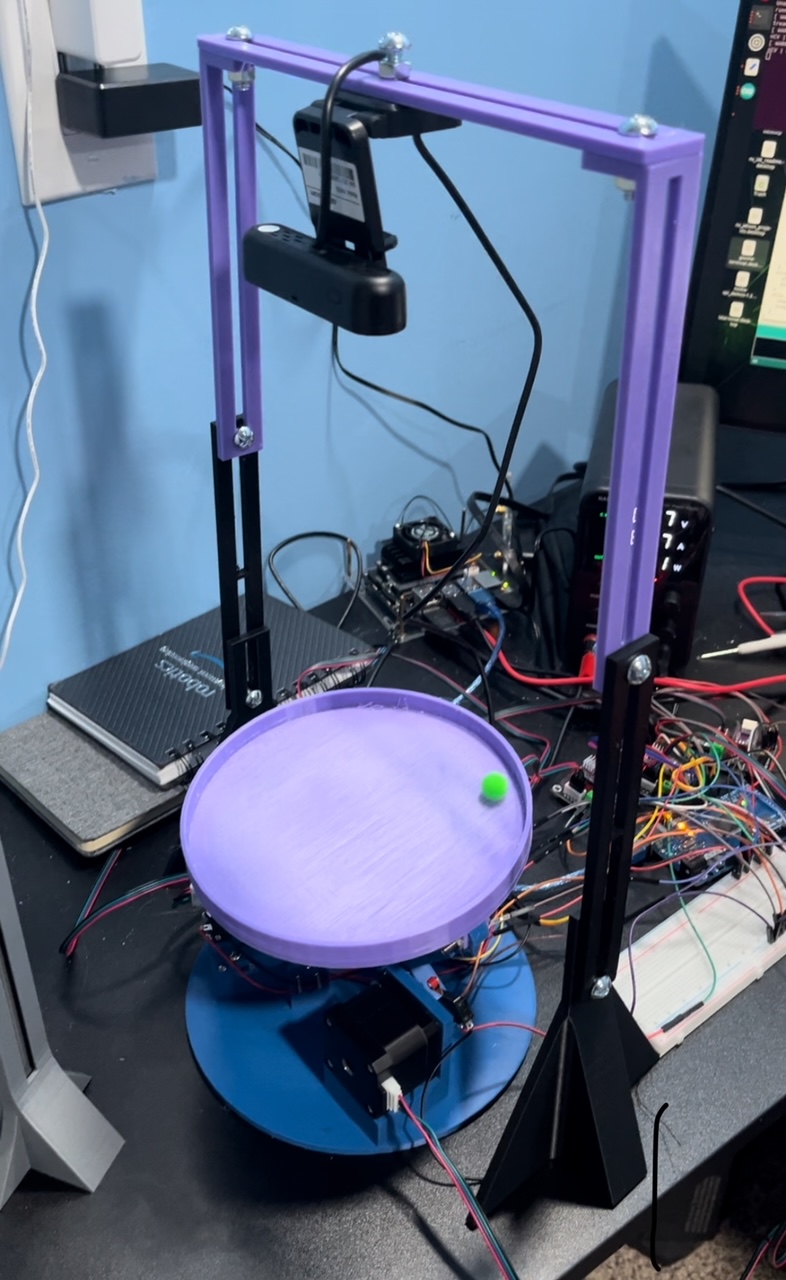
To balance a ball to remain at the center of a platform by adjusting the angles via 3 stepper motors. The motors react based on the ball positional input given from an overhead camera that uses OpenCV to monitor the x and y position of the ball as it moves around the platform.
The controls of the robot can be split into 3 sections:
1. OpenCV Detection (Image --> (x,y) Ball Position)
2. Kinematics ((x,y) Ball Position --> Platform Angles/Error)
3. PID controller (Platform Angles/Error --> Motor Speeds)
Mechanical Design
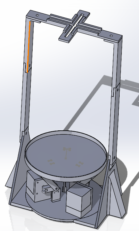
CAD Design --> Mechanical Assembly
I iteratively designed the mechanical components using Solidworks, then simulating it in an assembly to verify structural compliance. I used a Prusa 3D printer to print the individual parts, and nuts and bolts to fix them together
Mechanical Components
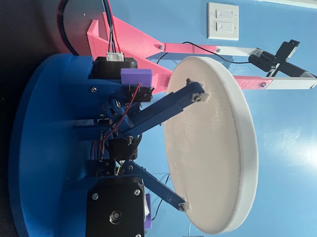
Leg and Stepper motor Configuration
I decided to configure the rotational functionality with 3 stepper motors situated at 120 degree angles from one another, and connected to the platform via two-jointed legs to produce a "contration" and "expansion" movement space.
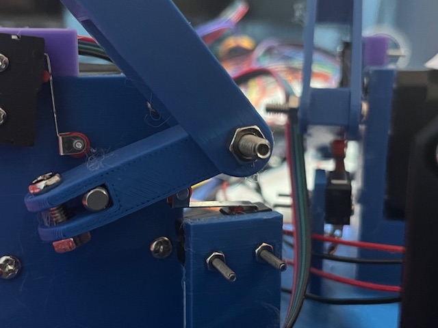
Limit Switch
To make sure the stepper motor wouldn't break the assembly from over actuating in either direction, I implemented limit switches at both ends of the rotation, with the logic that if the limit switch is hit, the motor should not run unless its direction is opposite to the limit switch position.
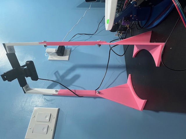
Camera Stand
I designed a custom camera stand for the overhead webcam. The camera needed to be at a set height (z-position) for optimal camera view of 19 inches. I needed to make the y-position adjustable to allow for room for error after the print came out, so I designed it to allow for adjustable y-position.
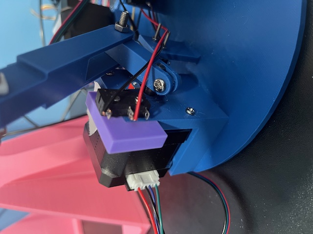
Limit Switch Retrofit
One key aspect of this project is the interative improvement process. In this example, I realized I didn't design a fixation spot for the upper-limit limit switch after I had fully printed out the base. Instead of being wasteful with 3D print material, I added a retrofit on the corner of the stepper motor holder as a minimal viable solution for fixating the limit switch.
Software/Electronics
Content for Software/Electronics section...
Gazebo Simulation